

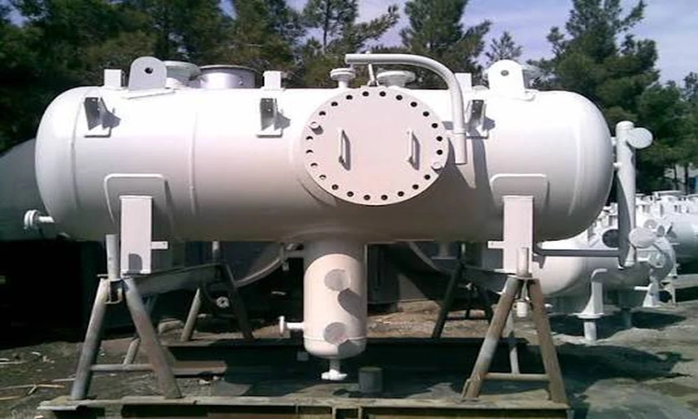
When a pressure vessel fails in service, the consequences rarely stay contained to the vessel itself. The surrounding equipment, the people nearby, and the facility as a whole absorb the impact. That reality is exactly why operating temperature and pressure ratings are treated so seriously in the pressure vessel industry, and why ASME pressure vessel fabrication follows a structured, code-driven process for establishing those limits from the very start of a project.
If you have ever wondered how a vessel ends up with a specific maximum allowable working pressure or a defined design temperature range, this article walks through the engineering logic behind it.
What “Rated” Actually Means
A common misconception is that pressure and temperature ratings are set conservatively as a matter of habit or general caution. In practice, they are calculated values, derived from specific material properties, vessel geometry, weld quality, inspection requirements, and the governing code standard.
Under ASME Section VIII, which covers most pressure vessels used in refining, chemical processing, and industrial manufacturing, the rated limits of a vessel are not arbitrary safety margins. They represent the conditions under which the vessel was specifically engineered and tested to operate. Exceeding those limits, even briefly, is not a gray area. It creates an out-of-compliance condition and can void certifications, trigger inspection holds, or cause equipment damage that affects the entire process system.
Understanding where those numbers come from matters whether you are specifying a vessel, reviewing a fabricator’s data sheet, or managing a plant turnaround.
The Role of Design Conditions vs. Operating Conditions
Before getting into the calculation methodology, it helps to distinguish between two terms that are sometimes used loosely in the field.
Operating conditions refer to the actual temperature and pressure at which the vessel runs during normal service. Design conditions are the values the vessel is engineered to withstand, and they are always set above the operating conditions by a deliberate margin. That margin accounts for process upsets, startup and shutdown swings, and any transient spikes that normal operations can produce.
Most engineering teams establish design conditions through a combination of process simulation data, historical operating data, and worst-case scenario analysis. The fabricator then builds to those design conditions. The result is a vessel rated for more than it will ever see in routine service, but only just enough more to remain practical and cost-effective.
This distinction also affects how design temperature is handled. You will see both a maximum design temperature and a minimum design metal temperature (MDMT) specified on a vessel data sheet. Both matter, and both have to be addressed in the fabrication process.
How Maximum Allowable Working Pressure Is Calculated
Maximum allowable working pressure, or MAWP, is the primary pressure rating for an ASME vessel. It represents the highest internal pressure the vessel is permitted to sustain at a designated temperature.
The calculation follows from the ASME Section VIII formulas, and the inputs include:
Shell thickness. The actual measured thickness of the shell after fabrication is the starting point. Code formulas use the actual thickness minus the specified corrosion allowance to get the effective thickness available for pressure containment.
Material allowable stress. Every approved material in the ASME code has a published allowable stress value at various temperatures. These values are listed in ASME Section II, Part D, and they reflect the material’s tested strength properties, with appropriate safety factors already applied. Carbon steel, low-alloy steel, and austenitic stainless alloys all have different stress tables, and the values decrease as temperature increases.
Vessel inside radius. Geometry directly affects pressure capacity. A larger diameter vessel with the same wall thickness will have a lower MAWP than a smaller diameter vessel, because the same pressure acts over a greater surface area.
Weld joint efficiency. This factor accounts for whether and how the welds were radiographically examined. A fully radiographed vessel receives a joint efficiency of 1.0, meaning full credit for the material’s strength. A vessel with no radiography may carry a joint efficiency as low as 0.70, which directly reduces the calculated MAWP. This is one of the reasons non-destructive examination is not just a compliance formality. It has a real, measurable effect on what the vessel can be rated to handle.
Putting those inputs together, the basic cylindrical shell formula for internal pressure produces the MAWP. Head calculations follow a similar logic but use different geometry factors depending on whether the heads are ellipsoidal, hemispherical, or flat.
After all components are calculated, the lowest value governs. The vessel’s MAWP is limited by its weakest point, whether that is the shell, a nozzle, or a welded connection.
How Temperature Ratings Are Established
Pressure and temperature are not independent variables in vessel design. They are linked because material strength changes with temperature.
The allowable stress values mentioned earlier drop as operating temperature increases. A vessel that is rated for a certain MAWP at 100 degrees Fahrenheit may only be rated for a lower MAWP at 700 degrees Fahrenheit using the same material, because the material is softer and weaker at elevated temperatures. This is why vessel data sheets include a table of pressure ratings at different temperatures, rather than a single flat rating.
Choosing materials that retain adequate strength at the intended design temperature is one of the more consequential decisions in vessel engineering. For standard service in carbon steel range temperatures, SA-516 Grade 70 is a common and well-understood choice. For elevated temperature service, low-alloy chrome-moly steels offer better creep resistance and elevated temperature strength. For cryogenic service, austenitic stainless steels or specialized low-temperature carbon steels are typically required to maintain ductility and toughness at low temperatures.
The minimum design metal temperature, or MDMT, is the lowest temperature at which the vessel is designed to operate under full pressure. Below the MDMT, the vessel’s material may become brittle, which dramatically changes its fracture behavior. Impact testing, typically Charpy V-notch testing, is often required to verify that the selected material meets toughness requirements at the specified MDMT. This is especially relevant for vessels in gas processing, cryogenic service, or outdoor northern climate installations.
External Pressure and Vacuum Considerations
Most engineers focus on internal pressure, which is the more intuitive case. But vessels that operate under vacuum or external pressure introduce an additional failure mode: buckling. A vessel shell under external pressure does not fail by rupture. It fails by collapsing inward, and the calculations for external pressure capacity are fundamentally different from internal pressure formulas.
ASME Section VIII includes separate design procedures for external pressure, and they involve geometric factors like the vessel’s length-to-diameter ratio and wall thickness-to-diameter ratio. Stiffening rings are often added to the shell to increase resistance to external pressure, and their placement is also governed by code.
Vessels used in vacuum distillation columns, condensers, and certain reaction systems fall into this category. Specifying a vessel for vacuum service without flagging it to the fabricator is one of the more common specification errors that leads to costly redesigns late in the project.
Why the Nameplate Matters
At the end of fabrication, every ASME code vessel receives a stamped nameplate that records the MAWP, design temperature range, MDMT, shell material, year built, and the certifying stamp. This nameplate is not decorative. It is a legal record of the vessel’s rated limits and the code under which it was built.
When a vessel is installed in the field, the operating limits shown on the nameplate define the boundaries within which the vessel must be operated. Any modification that changes those limits, whether through a nozzle addition, a service change, or a pressure increase, requires an engineering review and may require rerating or requalification under code.
For plant engineers and reliability teams, keeping records of vessel nameplates and associated data packages is part of responsible asset management. The data package, which includes mill certifications, weld records, inspection reports, and NDE documentation, is what makes the nameplate numbers verifiable and defensible.
What This Means for Procurement and Project Teams
When you are sourcing a pressure vessel, understanding how ratings are determined helps you ask better questions and write better specifications.
Providing complete design conditions, including design pressure, design temperature, MDMT, corrosion allowance, and any special service requirements, up front allows a fabricator to select appropriate materials and design to the correct code division from the beginning. Leaving any of those inputs undefined tends to generate clarification questions mid-project, which delays drawings, delays material procurement, and ultimately delays delivery.
If you are replacing an existing vessel and have the original data sheet, providing it to the fabricator is one of the most efficient ways to start the conversation. If you are designing for new service, working with your process engineer to produce a complete process data sheet before issuing the RFQ will save time on both sides.
Closing Thoughts
Operating temperature and pressure ratings for ASME vessels are the output of a disciplined engineering process, not conservative guesswork. They reflect real material behavior, real geometry, and real code requirements. For the engineers and procurement teams who specify and source these vessels, knowing how those numbers are derived makes it easier to communicate clearly, catch errors early, and hold fabricators accountable to the right standard.
The detail that goes into establishing a vessel’s rated limits is part of what makes ASME code fabrication a meaningful specification, and it is part of what separates a properly engineered vessel from one that simply looks the part.